SS-V: 1010 Twisted Cantilever Beam
Test No. VS02 Find tip deflections of a twisted cantilever beam when subjected to shear loads.
Definition
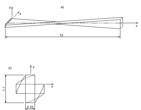
A cantilever beam, twisted by 90 degrees, is subjected to two different until loads at the
free end (Figure 1):
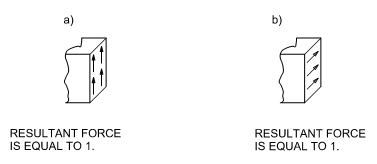
- in-plane shear
- out of plane shear
Loads are uniformly distributed along the face.
The units are IPS.
The material properties are:
- Properties
- Value
- Modulus of Elasticity
- 29e+6 psi
- Poisson's Ratio
- 0.22
Results
The following table summarizes the tip displacements [in].
| Theory (beam theory) | SimSolid | % Difference | |
|---|---|---|---|
| In-plane Shear (+Y direction) | 5.4240E-03 | 5.4540E-03 | 0.55% |
| Out-of-plane Shear (+ X direction) | 1.7540E-03 | 1.6291E-03 | -7.12% |
1 MacNeal, R.H., and
Harder, R.L., A Proposed Standard Set of Problems to Test Finite Element
Accuracy, Finite Elements in Analysis and Design, 1 (1985)
3-20.